Servos
Overview
Servo motors (servos) are available in a wide range of sizes and capabilities. A servo makes it easy to add controlled motion to a project.
Servo Components
A typical servo has four components:
- Motor
- Control unit
- Gears
- Horns
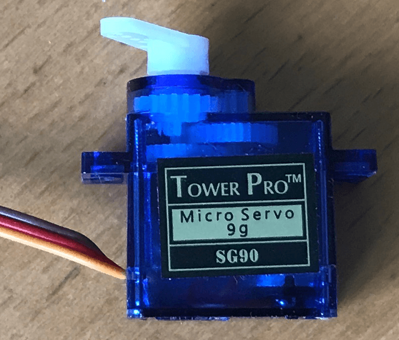
The motor provides the motion turning the spindle. Gears connect the spindle from the motor to the project. A small controller board translates the signals from the Netduino into a position for the spindle. All of this in a small package:
The horns provide a way to connect the spindle from the servo to the rest of the project. Servos are normally supplied with several horns allowing a number of methods to connect the servo:
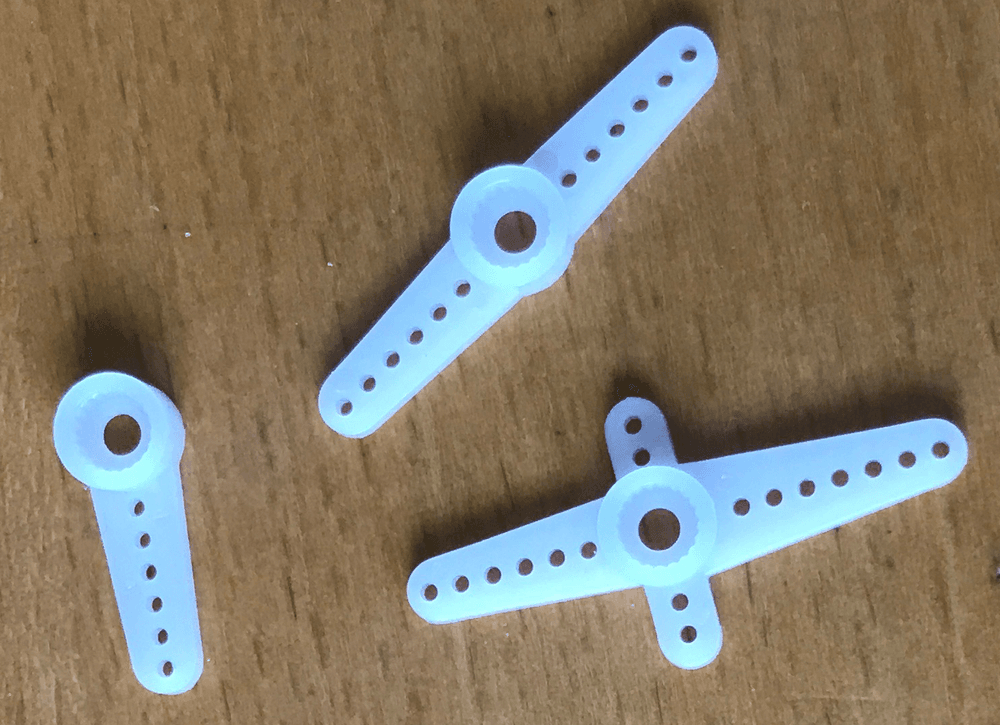
The holes in the armatures of the horns allow cables and wires to be connected to the horns. This makes it possible to translate the circular motion of the servo into linear motion to control a rudder on a boat or plane.
Wiring
Three wires are used to connect the servo to the Netduino:
- Power
- Ground
- Control signal
The servo above uses a 5V power supply. According to the data sheet the control signal should be 4.8V - 5V. However, in practice, the 3.3V signal from a Netduino PWM pin can be used without issue.
Types of Servo Motors
The two common types of servos are:
- Fixed range
- Continuous rotation
Fixed range servos have a defined sweep, typically 0 to 180 degrees. Fixed range servos typically have hard stops built into the case. Care should be taken not to attempt to rotate the motor past these stops.
Continuous rotation servos act similar to a standard DC motor rotating in either direction continuously.
Netduino.Foundation Support
Netduino.Foundation includes a Servo Core library that greatly simplifies servo control. This hardware guide is here for reference purposes, but we strongly recommend using the Server Core library to control them.
Control Signals
A typical servo uses a 50Hz signal to control the position of the servo. The position is determined by the width of the high pulse of the signal so a control signal will look something like this:

This makes PWM ideal to control a servo. Code to set the initial position of a servo is as simple as this:
pwm = new PWM(Pin, 50.0, 0.05, false);
pwm.Start();
Changing the position is as simple as changing the duty cycle of the pulse:
pwm.DutyCycle = 0.07;
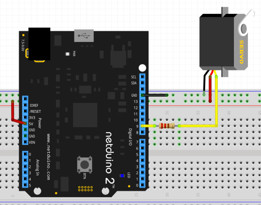
Connecting the Servo Using Breadboard
Only three connections are required:
- Power
- Ground
- Control signal
For a low power servo, the power and ground signal can be connected directly to the Netduino 5V lines. It is advisable to connect the control signal through a current limiting resistor, in the case of the Microservo SG90 a 470Ω resistor was used to connect digital pin 9 to the control signal of the servo.
Sweeping Through 180 Degrees using the Netduino.Foundation Servo Core Library
The SG90 servo pictured above is capable of sweeping through 180 degrees. The stated pulse width is 1ms (0 degrees) to 2ms (180 degrees). The following code uses the Netduino.Foundation Servo Core library to sweep the server from 0º to 180ª and then back to 0º:
using System.Threading;
using SecretLabs.NETMF.Hardware.NetduinoPlus;
using Netduino.Foundation.Servos;

namespace ServoTest
{
    public class Program
    {
        public static void Main()
        {
            Servo servo = new Servo(PWMChannels.PWM_PIN_D9, 1000, 2000);
            while (true)
            {
                for (int angle = 0; angle <= 180; angle++)
                {
                    servo.Angle = angle;
                    Thread.Sleep(40);
                }
                for (int angle = 179; angle > 0; angle--)
                {
                    servo.Angle = angle;
                    Thread.Sleep(40);
                }
            }
         }
    }
}
where the Servo class allows the angle of the servo to be set.
Low-Level Code to Change the Angle
The following descriptions taken from the data sheet of the Microservo SG90 used in this project. The terms will be common to most servos but the exact values should be taken from the servo data sheet.

The frequency of the signal is 50Hz giving a period of 20,000 microseconds (20 ms).
The pulse width determines the position of the servo. This should be between the minimum and maximum pulse width.
From the data sheet of the Microservo SG90, the minimum pulse width is 1ms (0 degrees) and the maximum pulse width is 2ms (180 degrees). So to calculate the pulse width for a specified angle the following steps should be followed:
- Pulse range = maximum pulse width - minimum pulse width
- Pulse width per degree = pulse range / 181
- For a specified angle, the pulse width = minimum pulse width + (angle * pulse width per degree)
For the Netduino this needs to be converted into a duty cycle. For an average servo, the pulse frequency is 50 Hz. The duty cycle for a specified angle becomes the pulse width / 20,000. In code this becomes:
double pulseWidth = MinimumPulseWidth + (_angle * ((MaximumPulseWidth - MinimumPulseWidth) / 181));
double dutyCycle = pulseWidth / 20000;
if (PWMPin == null)
{
    PWMPin = new PWM(Pin, SERVO_FREQUENCY, dutyCycle, false);
    PWMPin.Start();
}
else
{
    PWMPin.DutyCycle = dutyCycle;
}
Why 181 in the pulseWidth calculation, there are 181 divisions as the angle is between 0 and 180 inclusive.
Practical Implementation
Whilst developing the Servo class it was noted that using the default values did not result in a 180 degree sweep. Experimentation with the servo showed that the servo had a wider pulse range. The constructor for the Servo class became:
Servo servo = new Servo(PWMChannels.PWM_PIN_D9, 500, 2400);