I2C Reading
Info
The previous section of this guide presented an overview of the I2C protocol. This section will demonstrate how to read some data from a sensor, specifically the TMP102 temperature sensor.
Netduino.Foundation I2CBus
The Netduino.Foundation framework contains an I2CBus class that makes I2C communication easy by encapsulating all of the low-level plumbing calls in an easy to use object. We recommend using that class for I2C communications rather than using the low-level calls directly.
Netduino I2C Pins
The Netduino has two pins allocated for the I2C protocol. These pins are labelled SD (for SDA) and SC (for SCL) and can be found above the 14 digital pins on the right of the board as viewed below:

TMP102 I2C Temperature Breakout Board
Use of the I2C bus on the Netduino will be illustrated using a temperature module. The TMP102 is a commonly available temperature module capable of measuring temperatures in the range -40°C to +125°C with a maximum resolution of 0.0625°C. This device uses I2C and can be powered by a 3.3V signal, ideal for use with Netduino.
Purchasing
TMP102 breakout modules can be purchased from Sparkfun.
Using I2C on the Netduino
Reading the current temperature from the TMP102 will illustrate the basic software requirements for successful communication with an I2C device, namely a simple read operation.
Wiring up the TMP102 and Netduino
Firstly, ensure that the Netduino is disconnected from power and the USB connector. Once complete, place the TMP102 into a piece of breadboard (you will need to solder male pins to the breakout board first).
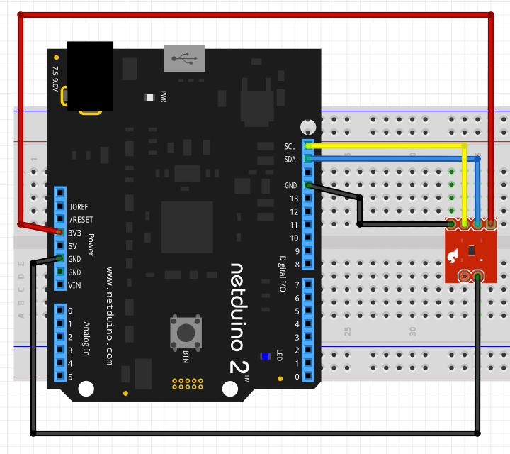
Next make the following connections between the temperature breakout board and the Netduino:
| TMP102 Pin Name | Netduino Pin Name | Wire Color in Photo Below |
|---|---|---|
| SDA | SD | Blue |
| SCL | SC | Yellow |
| Vcc | 3.3V | Red |
| GND | GND | Black |
| ADD0 | GND | Black |
Software
Open Visual Studio (or Xamarin Studio) and follow the instructions on the Getting Started page and start a new project. Copy the following code and paste it into the program.cs file replacing the default code.
using Microsoft.SPOT;
using Microsoft.SPOT.Hardware;
using System.Threading;

namespace TMP102
{
    public class Program
    {
        public static void Main()
        {
            //
            //  Create a new I2C device for the TMP102 on address 0x48 with the clock
            //  running at 50 KHz.
            //
            I2CDevice tmp102 = new I2CDevice(new I2CDevice.Configuration(0x48, 50));
            //
            //  Create a transaction to read two bytes of data from the TMP102 sensor.
            //
            byte[] buffer = new byte[2];
            I2CDevice.I2CTransaction[] reading = new I2CDevice.I2CTransaction[1];
            reading[0] = I2CDevice.CreateReadTransaction(buffer);
            while (true)
            {
                //
                //  Read the temperature.
                //
                int bytesRead = tmp102.Execute(reading, 100);
                //
                //  Convert the reading into Centigrade and Fahrenheit.
                //
                int sensorReading = ((buffer[0] << 4) | (buffer[1]) >> 4);
                double centigrade = sensorReading * 0.0625;
                double fahrenheit = centigrade * 1.8 + 32;
                //
                //  Display the readings in the debug window and pause before repeating.
                //
                Debug.Print(centigrade.ToString() + " C / " + fahrenheit.ToString() + " F");
                Thread.Sleep(1000);
            }
        }
    }
}
Reconnect the Netduino to the USB cable then save and run the application. If everything has been connected correctly you will start to see temperature measurements in the Application Output / Debug window.
Key Elements
The data sheet for the TMP102 states that the default address for the TMP102 is 0x48, so the first task is to create a new I2CDevice object that defines how we connect to the TMP102:
I2CDevice tmp102 = new I2CDevice(new I2CDevice.Configuration(0x48, 50));
The above code creates the tmp102 object where the device has an address of 0x48 and the communication speed will be 50KHz.
Temperature readings are returned from the TMP102 as a two byte value and so a buffer is needed to store the results of the read operation:
byte[] buffer = new byte[2];
NETMF uses transaction to communicate with I2C devices. Using an array of transactions allows multiple operation to be completed at the same time. In this case, there is only one read operation and the array of transactions consists of a single element:
I2CDevice.I2CTransaction[] reading = new I2CDevice.I2CTransaction[1];
reading[0] = I2CDevice.CreateReadTransaction(buffer);
More complex cases allow multiple operations to be executed as a simple operation simply by adding more transactions to the array.
In the above code, an array reading is created to hold the single transaction that should be executed. Two transaction types are supported and these are created with the I2CDevice.CreateReadTransaction and the I2CDevice.CreateWriteTransaction methods.
At this point the initialization and set up is complete. The main program loop is entered and the temperature reading is read repeatedly using the following statement:
int bytesRead = tmp102.Execute(reading, 100);
The Execute method above takes an array of transactions, in our case the single read transaction and a timeout value in milliseconds.
The remainder of the code simply calculates the temperature using the formula derived from the data sheet.
Program Output
Successful deployment of the application should reduce in a stream of temperature readings, one per second:
22.5625 C / 72.612500000000011 F
22.5625 C / 72.612500000000011 F
22.5625 C / 72.612500000000011 F
22.5625 C / 72.612500000000011 F
22.5625 C / 72.612500000000011 F
22.5625 C / 72.612500000000011 F
Logic Analyser Output
The output from the Netduino can be interpreted by using a logic analyzer.
The logic analyzer was configured to read data for two-seconds. The data was then processed by an I2C protocol decoder. This resulted in the following trace:

The trace has been annotated to indicate the signal line and the protocol being analyzed.
Starting from the left of the data signal:
- Start bit indicated by the green dot
- Device address and access mode (0x91)
- Two data bytes (0x15 and 0xC0)
- Stop bit indicated by the red dot
It is interesting to note that the device address and mode byte are encoded with the device address transmitted first followed by the mode bit. I2C uses 1 to represent a read transaction and 0 to represent a write transaction.
In the case of the above application, the address is 0x48 and Netduino is reading from the device. Read mode is indicated by a 1 and write by a 0. This results in a packet header of 0x91:
| Item | b7 | b6 | b5 | b4 | b3 | b2 | b1 | b0 | Notes |
|---|---|---|---|---|---|---|---|---|---|
| Device address | 1 | 0 | 0 | 1 | 0 | 0 | 0 | 0 | Device address shifted left by one place |
| Read / Write indicator | 0 | 0 | 0 | 0 | 0 | 0 | 0 | 1 | Read = 1 |
| Packet header | 1 | 0 | 0 | 1 | 0 | 0 | 0 | 1 | Address or-ed with mode bit = 0x91 |
When reading the logic analyzer traces, read operations to this device have the first byte set to 0x91 whilst write operations to the same device have the first byte set to 0x90.
Writing Data Using I2C
The next section of this guide will reconfigure the TMP102 temperature sensor by writing some data to the sensor.
Further Information
- This Wikipedia article contains a description of the protocol, the various modes and the bus characteristics.
- Pull up resistors
- Effects of Varying I2C Pull-Up Resistor (external link)
- Netduino.Foundation
I2CBus