SPI Writing
Info
The SPI guide demonstrated simple data transmission using SPI. This guide demonstrates using the SPI protocol to communicate with an LCD display fitted with an SPI backpack via an examination of the µLiquidCrystal library's SPI LCD implementation.
Netduino.Foundation Display Drivers
If you're looking to use an LCD display with Netduino, we recommend using the various display drivers available via Netduino.Foundation. They provide an easy to use API for various displays. This guide is meant as an informational resource to explain the low-level workings of the SPI protocol.
LCD Displays
LCD displays provide a simple and convenient way to present information to the user of a project. The range of products and their relatively low cost make them ideal for this purpose.
LCD displays are often referred to by the number of lines and characters that they can display. Common sizes are:
- 8 x 2
- 16 x 2
- 20 x 4
The first number represents the number of characters on each line and the second is the number of lines.
Some displays will have higher numbers such as 128 x 64. In these cases the numbers refer to the number of pixels on the horizontal and vertical axises.
This guide will concentrate on character LCD displays.
LCD Display Interface (HD44780)
The common interface for the LCD displays is the HD44780 LCD Interface. This uses up to 16 pins including the power and ground pins.
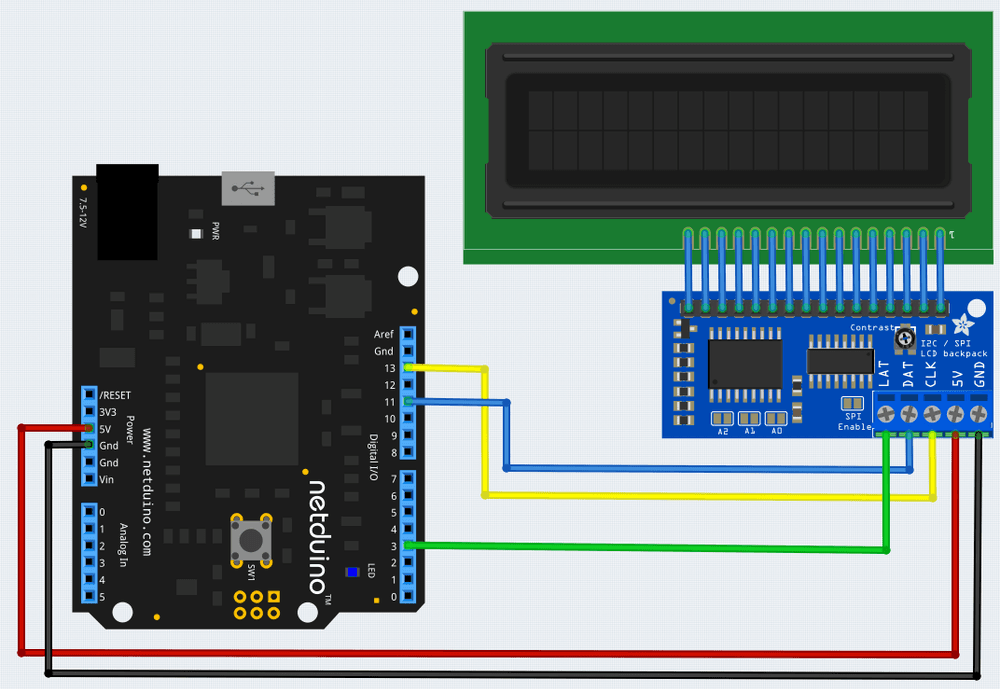
The Adafruit I2C/ SPI Character LCD Backpack can be used to reduce the number of pins required to only 5 (including power and ground). There are obvious advantages to this approach as fewer pins are used allowing the remaining pins to be used to communicate with sensors etc.
The HD44780 protocol is involved, for instance, the following code is required to set the interface into 4-bit mode:
// we start in 8bit mode, try to set 4 bit mode
SendCommand(0x03);
Thread.Sleep(5);   // wait min 4.1ms

SendCommand(0x03);
Thread.Sleep(5);    // wait min 4.1ms

// third go!
SendCommand(0x03);
Thread.Sleep(5);

// finally, set to 4-bit interface
SendCommand(0x02);
Luckily, there is a library that encapsulates all of this complexity. The above sequence of calls along with the remaining code required to set up the display becomes:
lcd.Begin(16, 2)
The lcd object here starts the communication with a 16 x 2 LCD display.
This library is the MicroLiquidCrystal library.
MicroLiquidCrystal Library
The MicroLiquidCrystal library is based upon the Arduino Liquid Crystal Library. The original implementation was documented on Szymon Kobalczyk's Blog.
The library wraps the numerous low level commands in higher level API calls. The following application shows how to setup the Adafruit LCD Display and display the current number of machine ticks since the Netduino was powered up:
using System.Threading;
using Microsoft.SPOT;
using Microsoft.SPOT.Hardware;
using SecretLabs.NETMF.Hardware.NetduinoPlus;
using MicroLiquidCrystal;

namespace HelloWorld
{
    public class Program
    {
        public static void Main()
        {
            var setup = new BaseShifterLcdTransferProvider.ShifterSetup()
            {
                BL = ShifterPin.GP7,
                RS = ShifterPin.GP1,
                RW = ShifterPin.None,
                Enable = ShifterPin.GP2,
                D4 = ShifterPin.GP6,
                D5 = ShifterPin.GP5,
                D6 = ShifterPin.GP4,
                D7 = ShifterPin.GP3
            };
            var lcdBus = new Shifter74Hc595LcdTransferProvider(SPI.SPI_module.SPI1, Pins.GPIO_PIN_D3,
                                                               Shifter74Hc595LcdTransferProvider.BitOrder.MSBFirst, setup);
            var lcd = new Lcd(lcdBus);
            lcd.Begin(16, 2);
            lcd.Write("Hello, world!");
            while (true)
            {
                lcd.SetCursorPosition(0, 1);
                lcd.Write((Utility.GetMachineTime().Ticks / 10000).ToString());
                Thread.Sleep(100);
            }
        }
    }
}
Wiring up the LCD Display
As noted, the backpack allows the Netduino to talk to the LCD using SPI. This requires three wires plus power connections. The LCD Backpack should be wired as follows:
Software
The MicroLiquidCrystal library allows a number of different way to connect to an LCD display. The mechanism used is defined by a Transfer Provider. In the cas of the Adafruit LCD Backpack this is a 74595 shift register. This register takes 8 data bits transmitted serially (using SPI) and presents them to the display as 8 parallel data bits.
The first section of code sets up the transport provider interface:
var setup = new BaseShifterLcdTransferProvider.ShifterSetup()
{
    BL = ShifterPin.GP7,
    RS = ShifterPin.GP1,
    RW = ShifterPin.None,
    Enable = ShifterPin.GP2,
    D4 = ShifterPin.GP6,
    D5 = ShifterPin.GP5,
    D6 = ShifterPin.GP4,
    D7 = ShifterPin.GP3
};
var lcdBus = new Shifter74Hc595LcdTransferProvider(SPI.SPI_module.SPI1, Pins.GPIO_PIN_D3,                Shifter74Hc595LcdTransferProvider.BitOrder.MSBFirst, setup);
The ShifterSetup class defines which lines of the shift register implement a particular function:
| Line | Function |
|---|---|
| BL | Back light |
| RS | Register Select |
| RW | Read/Write |
| Enable | Clock enable |
| D4-D7 | Data bits 4-7 |
The module will be configured to only require 4 data bits. The library will split each byte into two parts and transmit the 4-bit data packets sequentially.
lcdBus is an instance of the shift register transport provider. This will send the data to the LCD display using SPI module 1. The remaining arguments configure the library to send the data with the most significant bit first. Pin D3 will be used to latch the data into the shift register.
The next task is to create an instance of the library and write some text to the display:
var lcd = new Lcd(lcdBus);
lcd.Begin(16, 2);
lcd.Write("Hello, world!");
The lcd object is set up to control a 16x2 LCD display and a greeting is displayed at the top of the display.
Finally, the main program loop updates the display with the current number of ticks since power was applied to the Netduino board.
while (true)
{
    lcd.SetCursorPosition(0, 1);
    lcd.Write((Utility.GetMachineTime().Ticks / 10000).ToString());
    Thread.Sleep(100);
}
The source code including the MicroLiquidCrystal source files can be found here.
Reading Data From an SPI Device
The next section of the guide on SPI will demonstrate how to read data from an SPI device.
Further Reading
- Serial Peripheral Interface Bus on Wikipedia.
- HD44780 LCD Interface This is a common interface used to drive LCD displays.
- Adafruit I2C/ SPI Character LCD Backpack
- 74595 shift register