General Diodes
Intro
As we examined in the last section, a diode is basically just a P-N junction with leads attached to either side. The anode (A) is the lead attached to the P-type side, the cathode (K) is attached to the N-type side, and the preferential, or forward bias is when electrons flow from cathode to anode (which means anode is hooked to the positive voltage source):

The symbol for a diode is a triangle pointing in the direction of current (hole-flow) connected to a perpendicular line which represents the junction:
 {:standalone }
There are a number of different types of diodes, but all of their circuit symbols are based on the one above.
The Wikipedia diode entry lists almost 20 different types of diodes, but in practice, most circuit design only uses a handful of them. As we explore more circuits, we'll also introduce additional, specialized diodes.
Polarity
To differentiate which end of a diode is the anode and which is the cathode, they usually have a marking on the end denoting the cathode. The following photo shows four different diodes, each with their cathode mark on the right:
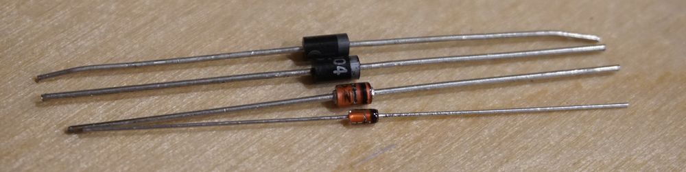
Recall that positive charge carriers (holes) flow preferentially from anode to cathode, so the diodes above are in the same orientation as the circuit symbol below:

Diode Characteristics
Depending on how they're constructed, a diode can have some interesting behaviors. For general diodes, there are a number of characteristics that are used to describe how they work:
- Forward Voltage (
Vf) - This is the amount of voltage drop, or the amount of voltage needed to enable current flow. - Maximum Forward Current (
If(max)) - This is the maximum amount of current that the diode can safely conduct when forward-biased without breaking. - Peak Inverse Voltage (PIV) or maximum reverse voltage (
VR(max)) - This is the maximum amount of voltage that can be applied in reverse bias without an avalanche breakdown. - Total Power Dissipation (
PD(max)) - A diode has some resistance, so some power is lost in the form of heat. As such, a diode usually has a maximum amount of power that it can safely conduct without overheating. Total power dissipation is based on the voltage of the junction potential and the current:PD=Vf*I. - Reverse Recovery Time (
Trr) - This is how quickly a diode can go fromOFFtoON. It's generally only important in fast-switching circuits.
Common General Diodes
- Switching Diodes - Also known as small signal diodes, they have an extremely fast
Trr, and are used for fast current switching. - Rectifier/Power Diodes - High current capacity, usually
1Aor more. Used for converting AC to DC and protection of circuits from power spikes. - Schottky Barrier Diodes - Have a very low voltage drop, so they can be used in a clever way to get to a digital
0/OFF. Also very fast. Used for basic logic control. - Zener Diodes - Have a precise breakdown voltage. Typically used in a reverse bias configuration to provide a voltage reference.
Switching/Small Signal Diodes
Switching diodes are one of the most common diodes available, largely because of their usefulness in high frequency circuits like radios, where their fast switching abilities are required.
They typically have small power ratings, 150mA or less, and a Vf of 0.7V.
Despite their commonality, most of the digital circuits we'll explore will use other diodes.
Power/Rectifier Diodes
Power (aka rectifier) diodes are similar to signal diodes but are designed to handle higher current. The 1N4001 is a common rectifier diode and is capable of handling 1A, but the Vf (forward voltage) drop is 1.1V. These are commonly used to protect certain parts of circuits from voltage spikes, as well as for conversion of AC to DC electricity.
Because diodes control the direction of current, they're often used to protect circuits from unwanted current, especially power spikes.
Flywheel Diodes
Flywheel diodes protect circuits from collapsing magnetic fields created by de-powering electric motors and other coils by feeding excess current back into the coil. We'll use a flywheel diode in a later chapter to safely control a relay.
Voltage Clamping
Voltage clamping refers to clipping a signal to a maximum/minimum value to prevent it from going outside a particular range, or shifting an entire AC signal wave above or below 0V.

Rectifiers
Alternating Current (AC) electrical signals can be converted into Direct Current (DC) through a clever arrangement of diodes known as a rectifier:

The above circuit will transform a two-phase AC wave form into positive and ground voltages:

With some additional components, the DC wave output above can be transformed into a smooth, level DC signal.
Rectifiers are used as the first stage in converting household mains AC current into DC current for use in electronics in nearly all AC power adapters. For example, the USB wall adapter that you use to charge your phone converts AC to DC using a rectifier. In fact, nearly every electronic device around you that plugs into the wall contains a rectifier circuit.
Schottky Barrier Diodes
Schottky diodes use a piece of metal against the N-type side instead of a P-type semiconductor. This results in a much lower voltage drop and fast switching speeds.
The circuit symbol for a Schottky diode looks similar to the diode symbol, except that the perpendicular line looks similar to an S.

Schottky diodes typically have a very low voltage drop (Vf), typically around 0.2V (0.15V to 0.45V) which makes them very fast and also makes them ideal for use in simple circuit logic.
Reverse Current Protection
Because diodes act like one-way valves, they can prevent reverse current from happening in situations where a battery is plugged in the wrong way. Schottky diodes are ideal for this because their low Vf means that it doesn't cost much battery voltage to protect the circuit.
Diode Logic Gates
These logic circuits can be arranged to provide operations such as AND and OR, called logic gates. This allows you to determine if multiple inputs are all ON as well as if any of the inputs are ON or OFF.
Consider the following circuits:

OR Gate Truth Table
Truth tables are used to describe the resulting output from inputs based on the operation/function. The following truth table describes the resulting output based on the possible inputs to an OR gate:
| Input 1 | Input 2 | Output |
|---|---|---|
| 0 | 0 | 0 |
| 0 | 1 | 1 |
| 1 | 0 | 1 |
| 1 | 1 | 1 |
In the truth table, 0 and 1 represent LOW and HIGH, respectively. In the case of our circuit, this means somewhere around 0V for LOW and 3.3V for HIGH.
In the case of an OR gate, as long as any input is 1, the output will also be 1. This makes sense, because applying voltage to either diode will provide voltage to the output.
However, recall from earlier that digital logic levels don't have to be exactly 0V and 3.3V, but rather, LOW can be up to 1.1V, and HIGH can be as low as 2.2V. This is important, because in a practical circuit implementation of the above, some voltage is actually lost to the voltage drop of the diode. If the Vf of the diodes are 0.2V, then only 3.1V is actually read on the output.
AND Gate Truth Table
The AND gate is a slightly more clever than the OR gate. In the case of the AND operation, a HIGH voltage is only seen at the output when both inputs are HIGH, therefore, blocking the ground path for the 3.3V voltage source:
| Input 1 | Input 2 | Output |
|---|---|---|
| 0 | 0 | 0 |
| 0 | 1 | 0 |
| 1 | 0 | 0 |
| 1 | 1 | 1 |
Logic Gate Uses
In this way, low Vf Schottky diodes can be used to determine if conditions are met within a circuit, such as if multiple inputs are ON. We'll explore this more by building these gates in one of this chapter's labs.
Zener Diodes
Zener diodes have a known, precise breakdown voltage, which makes them very useful for providing a reference voltage.
Voltage Reference
Sometimes, a circuit needs a reference signal at a precise voltage. By utilizing the breakdown voltage of a reverse-biased Zener in a circuit, its Vf back-pressure can provide that voltage reference. Consider the following circuit:

In the circuit above, a Zener with a 5V breakdown voltage is being reverse biased with 9V, which means that it's breakdown threshold has been reached, and will conduct current, with a 5V voltage drop. Since the voltage drop acts like a dam, no matter how much voltage is applied, 5V of back pressure will always be present:

As long as the current is limited, in this case with a resistor, it will stay within that precise operating band. Recall the diode behavior chart from before, specifically the breakdown behavior:

While this circuit looks a lot like a two resistor voltage divider, it's got a huge advantage over a divider; as long as the current is limited, no matter what amount of voltage is applied (within the diode's tolerance), the Vout reference will always be the same.
And while the limited amount of current prevents this from being a useful voltage regulator, it does serve as a reliable voltage reference, which is used in ADC conversions, voltage regulator circuits, and more.
Zener Diodes come in many Reverse Voltage Ratings
Because Zener diodes are often used as voltage references, they come in a wide variety of reverse voltages. In fact, Zeners cover all common voltages you're likely to find in modern circuits.