Voltage Divider Practicals
Common Uses
Voltage divider circuits have a variety of uses, but for the type of practical circuitry that we're concerned with, they serve two primary functions: reading resistive sensors and analog level shifting.
Reading Resistive Sensors
A non-obvious usage for voltage dividers is for reading resistive sensors. Resistive sensors are specialized resistors that have a variable resistance depending on whatever input they're sensing. For instance, a photoresistor may have 30kΩ of resistance in the dark, but only 1kΩ of resistance in bright sunlight. There's no way to measure resistance directly with a Netduino, but if the resistive sensor is put in place of one of the resistors in a voltage divider circuit, the Vout voltage can be read, and the sensor's resistance can be calculated based on the known resistance of the other resistor in series:

Analog Level Shifting
Another common use of voltage dividers is to adjust, through division, the level of an analog input signal to a lower level.
For instance, a 5V analog temperature sensor may output 0V to 5V, depending on the temperature that it's sensing. At the highest temperature it can sense, it might output a 5V signal, 0V at the lowest temperature, and voltage in between representing temperatures between those two points.
However, Netduino has analog inputs that can read voltage from 0V to 3.3V. So in order to convert (or level shift) the signal from a 5V sensor to a 3.3V analog input, it needs to be divided:

In practice, very few sensors are 5V anymore (lower voltage is faster and can be used on smaller circuits; most modern CPUs run internally at 1.2V or less), but occasionally you might find an older 5V sensor that you want to use.
Potentiometers
In addition to the divider circuits used in level shifting and resistive sensors, voltage division is used internally in potentiometers, which are knobs or sliders that provide a variable voltage output based on the adjustable resistance of the internal variable resistor. Potentiometers are often used on electronic devices to provide user input, for example, the volume on a stereo is often controlled by a potentiometer. The following image shows a traditional potentiometer on the left and a trimmer potentiometer (trimpot) on the right:
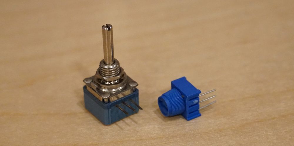
Potentiometers often have a decorative knob (for instance, a volume knob) attached to them after they're installed in their finished products. Trimpots are usually used internally in products to provide very precise adjustments, often to balance circuits. They're not meant for daily use, and often their lifespan is no more than 200 cycles/turns.
Practical Considerations
Whether voltage dividers are used to level shift or read resistive sensors, there are some practical considerations that must be understood before they can be used effectively.
Load and the Third Leg
When a load is attached to Vout, the values of the voltage divider circuit change. This is because a load has resistance, and that means that R2 + Load becomes a parallel resistance circuit:

Therefore, when calculating the divider resistance, the resistance of the load must also be considered.
For instance, if we were to use the voltage divider discussed earlier (in which R1 = 8Ω and R2 = 12Ω), and the load had a fixed resistance of 3Ω, we can calculate the total resistance of the bottom half of the divider by adding together the conductance of R2 and RLoad (recall that parallel resistance is calculated by adding together the conductance, or G, in siemens (S), which is the reciprocal of resistance):
Given:
Conductance (G) = 1 / R
G of R2 = (1 / 12Ω) = 0.083S
G of RLoad = (1 / 3Ω) = 0.33S

Therefore:
Total G = 0.083S + 0.33S = .42 S
Total Resistance of Load and R2 =  1 / 0.42 = 2.4Ω
So instead of getting 3V to the load, if we calculate Vout, we'd actually get something much smaller:
Given:
Vout = Vs * (R2 / (R1 + R2))

And:
R2 now = R2 + RLoad

Therefore:
Vout = 5V * (2.4Ω / 10.4Ω)) = 1.15V
As illustrated above, a 3Ω resistance in the load made a big difference; in this case, the load would only see 1.15V! And because the total resistance has changed, the amount of power would have also changed.
Netduino Analog to Digital Converter (ADC) Load
In both the level shifting and the resistive sensor, the values are read by Netduino via the Analog to Digital Converter (ADC) on the STM32F microcontroller, which is the main processing chip. An ADC reads voltage signals and converts them to a digital value that describes the input voltage level (0V to 3.3V) in 1,024 steps of precision (values 0 through 1,023).
Netduino has 6 analog inputs and the following code illustrates reading a voltage input level on Analog Pin 3:
AnalogInput analog3 = new AnalogInput(Pins.GPIO_PIN_A3)
int value = analog3.Read();
A value of 0 means that it read 0V, and a value of 1,023 means that the voltage was at or above 3.3V. The steps in between are linear; a value of 511, which is 1,023 / 2, indicates it was reading 1.65V, or 3.3V / 2.
The maximum voltage level that can be read is 3.3V, but the analog input ports are 5V tolerant, meaning they can accept up to 5V without overloading the chip and possibly destroying it. However, to be able to read any voltage above 3.3V, a voltage divider must be used.
ADC Resistance and Load
The ADC is a complex and clever circuit and getting accurate readings from it requires special considerations which will be covered in a later part of this tutorial. However, for prototyping purposes, we can ignore those complexities and design with simple concepts in mind.
When using a voltage divider with Netduino's analog input, we have to consider that the ADC has some resistance and requires a certain amount of current to work.
For prototyping purposes, we can assume that the ADC will provide about 11kΩ in resistance (actually impedance, which we'll learn about later). Using Ohm's law, we can then calculate that it will require up to 0.3mA of current:
Given:
I = V / R
V = 3.3V
R = 11kΩ

Therefore:
I = 3.3V / 11,000Ω = 0.0003 = 0.3mA
Additionally, 11kΩ is about 0.0001S (Siemens):
G = 1 / 11,000Ω = 0.00009S ~= 0.0001S
Luckily, even though the ADC adds resistance to the bottom half of the divider, the resistance is high enough that it has only a negligible effect, as we'll see.
Variable Load Resistance
Another complication of voltage dividers is that the consideration of load resistance gets much more complex when the resistance of that load can change over time. For instance, some sub circuits might draw different amounts of power depending on what the circuit is doing. In fact, the ADC does just that, but for prototyping we can largely ignore the fluctuation. Later on, we'll dive deeper into increasing the accuracy of analog readings.
One way to get around this is to use much smaller resistors in the divider so that there is lots of power going through the circuit and the third leg has a negligible effect. This might not make sense at first blush, but if we remember that the third leg is a parallel circuit, and therefore we add the inversion of the resistance (conductance), smaller resistors suffer less overall voltage modification.
For instance, given that the 11kΩ resistance of the ADC provides a very small amount of conductance, 0.0001S, an R2 resistor that's ~10x smaller, or 1kΩ, conducts nearly 10x more power (a conductance of 0.001S). This means the overall resistance of the bottom half of the divider is only affected by ~10%, going from 1,000Ω for the R2 alone, to 909Ω, when factoring in the ADC:
Given:
ADC = 11kΩ = 0.0001S
R2 = 1kΩ = 1 / 1000Ω = 0.001S

Therefore:
ADC + R2 = 0.0001S + 0.001S = 0.0011S = 909Ω
This means that as the load resistance changes, it only has a minor effect on the level of output voltage (Vout).
Power Efficiency
This reveals another interesting fact about voltage dividers; in their simple form, they are very power inefficient. Using smaller resistors to account for load resistance changes means that more power is wasted.
In circuit designs that require a high level of ADC accuracy, or more power efficiency, we can use a more complex circuit that uses an operational amplifier (OpAmp) to amplify the sensor signal so that we can use a very small amount of power. We'll explore that circuit in a later part of this tutorial. Again, for prototyping, we can usually get away with just using more power. We can also average our samples to get a cleaner reading, as we'll see in a bit.
Never use a Voltage Divider as a Voltage Regulator
Because of their inefficiency, voltage dividers should never be used as voltage regulator. In order to get a voltage signal that had only 10% deviation from the target value, you would have to use resistors that let 10x of the amount of power that the Vout required. So if the sub circuit required 100mA of power, then you would need to push 1A through the circuit to get a deviation between 95mA and 105mA.
Instead, cheap voltage regulator chips are much more efficient than a voltage divider to provide sub circuits with clean, regular power.