MicroGraphics Library
The Meadow.Foundation MicroGraphics library, formerly known as GraphicsLibrary, is an ultra-lightweight, 2D drawing framework that can draw to off screen (in-memory) display buffers and then present them on pixel display devices.
MicroGraphics includes the ability to draw many different primitives such as lines, shapes, text (using bitmap fonts), as well as bitmap images. Note - It can also be used to display JPEGs by using the open-source SimpleJpegDecoder nuget package.
Additionally, it implements ITextDisplay, so it enables any graphic display to be a canvas for use with the TextDisplayMenu library, easily enabling menus to be created and displayed on graphics displays.
To use the graphics display you:
- Initialize it with a display.
- Draw your graphics to the canvas (in-memory display buffer).
- Call
Show()to copy the canvas content to the display.
Initializing the MicroGraphics Library
In Meadow.Foundation, every graphics display driver manages its own buffer, since each display has different requirements in terms of display size, color depth and byte order.
For this reason, an initialized display driver must be passed to the MicroGraphics instance during construction. For example, the following code creates a graphics library canvas from the ST7789 display that can be found in the Hack Kit:
MicroGraphics canvas;

var display = new St7789(
    spiBus: Device.CreateSpiBus(),
    chipSelectPin: Device.Pins.A03,
    dcPin: Device.Pins.A04,
    resetPin: Device.Pins.A05,
    width: 240, height: 240,
    colorMode: ColorMode.Format16bppRgb565);

// create our graphics canvas that we'll draw onto
canvas = new MicroGraphics(display);

// finally, clear any artifacts from the screen from boot up
canvas.Clear(true);
Setting Display Rotation
Note that you can also set the rotation of display, which allows you to match the physical orientation of the display in your project:
canvas.Rotation = RotationType._270Degrees;
Canvas and Painter's Model
The MicroGraphics Library utilizes the painter’s model. That means that as you draw onto the drawing surface, each subsequent drawing operation is applied on top of the previous. For this reason, it's useful to think of an instantiated MicroGraphics class as canvas that you'll draw to.
Unlike layers in programs like Photoshop, once you have drawn something, you can’t undraw it, or remove layers. If you want to build an application like that, you either need to store a list of your draw operations and then re-draw each of the ones that you want to apply.
Clearing the Canvas
Drawing happens in-memory on the graphics canvas and is then sent to the display. After initializing the display, it's a good idea to call Clear() on the canvas to make sure the screen doesn't have any leftover artifacts from initialization:
canvas.Clear(updateDisplay: true);
Passing true for the updateDisplay parameter copies the cleared canvas to the display immediately. If you pass false (or don't pass anything at all), the canvas in memory will be cleared but the screen itself will not be cleared immediately until Show() is called.
Copying the Canvas to the Display
And after you've finished the drawing operations on the canvas, it can be pushed to the display via the Show() method:
canvas.Show();
Coordinate System
MicroGraphics uses a standard X/Y cartesian coordinate system for drawing and placing elements, with the origin (0,0) in the top left of the canvas. Increasing the X and Y coordinate moves right and down, respectively.

Each integer point represents an actual pixel, there is no pixel density scaling.
Drawing Primitives
There are a number of drawing methods available for drawing of various primitive including:
- Pixel
- Line
- Arc
- Path
- Triangle
- Circle
- Rectangle
- RoundedRectangle
- HorizontalGradient
- VerticalGradient
DrawLine
Draws a colored line:
graphics.DrawLine(
    x0: graphics.Width / 3,
    y0: graphics.Height / 3,
    x1: graphics.Width * 2 / 3,
    y1: graphics.Height * 2 / 3,
    color: Color.Red);
The code sample above draws a red diagonal line:

DrawArc
Draws a colored arc with the provided (x,y) origin, radius, and start and end angle:
graphics.DrawArc(
    centerX: graphics.Width / 2,
    centerY: graphics.Height / 3,
    radius: graphics.Height / 3,
    startAngle: new Meadow.Units.Angle(-90),
    endAngle: new Meadow.Units.Angle(90),
    color: Color.Red);
The code sample above draws the following arc:

DrawTriangle
Draws a colored line:
graphics.DrawTriangle(
    x0: graphics.Width / 3,
    y0: graphics.Height / 3,
    x1: graphics.Width * 2 / 3,
    y1: graphics.Height / 3,
    x2: graphics.Width / 2,
    y2: graphics.Height * 2 / 3,
    color: Color.Red,
    filled: true);
The code sample above draws a red triangle:

DrawCircle
Draws a colored circle:
graphics.DrawCircle(
    centerX: graphics.Width / 2,
    centerY: graphics.Height / 2,
    radius: graphics.Height / 3,
    color: Color.Red,
    filled: true);
The code sample above draws a filled red circle:

DrawRectangle
Draws a colored rectangle:
graphics.DrawRectangle(
    x: 20,
    y: 20,
    width: graphics.Width - 40,
    height: graphics.Height - 40,
    color: Color.Red,
    filled: true);
The code sample above draws a red rectangle:

DrawRoundedRectangle
Draws a colored rectangle with rounded corners:
graphics.DrawRoundedRectangle(
    x: 20,
    y: 20,
    width: graphics.Width - 40,
    height: graphics.Height - 40,
    cornerRadius: 20,
    color: Color.Red,
    filled: true);
The code sample above draws a red rectangle with rounded rectangles:

DrawHorizontalGradient
Draws a horizontal gradient pane:
graphics.DrawHorizontalGradient(
    x: 20,
    y: 20,
    width: graphics.Width - 40,
    height: graphics.Height - 40,
    colorLeft: Color.Red,
    colorRight: Color.Green);
The code sample above draws a horizontal gradient from Red to Green:

DrawVerticalGradient
Draws a vertical gradient pane:
graphics.DrawVerticalGradient(
    x: 20,
    y: 20,
    width: graphics.Width - 40,
    height: graphics.Height - 40,
    colorTop: Color.Red,
    colorBottom: Color.Green);
The code sample above draws a vertical gradient from Red to Green:

Drawing Images
MicroGraphics includes the ability to draw bitmap images via the DrawBitmap() method.
Make Images Available to Code
In order to use images with MicroGraphics, you need to make them available to your app. The common way to do this is to embed image assets as resources in your .NET project.
Add the image to your project structure. For Visual Studio 2022, you can also right-click a solution folder and select Add > Existing Item... and find your image file to copy it into the project.
Make the image an embedded resource copied to output directory.
In Visual Studio 2022...
- Select the image in Solution Explorer.
- Within the Properties panel, change the Build Action to Embedded resource.
- Also within the Properties panel, change the Copy to Output Directory setting to Copy if newer.
In Visual Studio Code...
Open the parent .csproj file.
Find or add an
<ItemGroup>where you will organize your embedded resources.Add an
<EmbeddedResource ...>element to the item group, setting the appropriateIncludeattribute and add a containing<CopyToOutputDirectory ...>element.<EmbeddedResource Include="images\logo.bmp">
<CopyToOutputDirectory>PreserveNewest</CopyToOutputDirectory>
</EmbeddedResource>
JPEG Decoding
We recommend using the SimpleJpegDecoder library to convert JPEG images into bitmaps for use with the MicroGraphics Library. For example, the following code illustrates how to load a JPEG image from a resource, store it in a BufferRgb888 object, and display it on screen:
var jpgData = LoadResource("meadow.jpg");
var decoder = new JpegDecoder();
var jpg = decoder.DecodeJpeg(jpgData);

var jpgImage = new BufferRgb888(decoder.Width, decoder.Height, jpg);

...

display.DrawBuffer(x, y, jpgImage);

display.Show();
Drawing Text
For performance and typical IoT display size reasons, MicroGraphics supports drawing text using bitmap fonts which define glyphs by their pixels, rather than their curves (as is done in fonts such as TrueType or OpenType). Meadow.Foundation includes a number of bitmap fonts.
graphics.CurrentFont = new Font12x20();
graphics.DrawText(x: 5, y: 5, "hello, Meadow!", Color.Black);
Text alignment
By default, text is left aligned with the x, y coordinates specifying the top left location of the rendered text. The vertical alignment of the text can be set at draw-time by setting the alignment parameter of DrawText. Horizontal Alignment can be set to Left, Center, or Right.
Leftwill render text with x, y coordinates specifying the top-left location of the rendered textCenterwill render text with x, y coordinates specifying the top-middle location of the rendered textRightwill render text with x, y coordinates specifying the top-right location of the rendered text
graphics.DrawText(x: 120, y: 0, $"Hello Meadow", alignment: TextAlignment.Center);
Scale Factor
To increase the size of a bitmap font, a 'ScaleFactor` can be optionally passed:
graphics.DrawText(
    x: 10, y: 10, text: text, color: Color.Black,
    scaleFactor: ScaleFactor.X2);
Drawing Paths
MicroGraphics has added basic path support modelled after SkiaSharp. A path is created by instantiating a GraphicsPath object and drawn using the DrawPath method.
GraphicsPath uses the concepts of verbs to control the path. It currently supports:
Movewhich sets the current positionLinewhich draws a line from the current position to a new positionClosewhich closes the current path by adding a line from the last position to the first position
var pathSin = new GraphicsPath();

for (int i = 0; i < 70; i++)
{
    if (i == 0)
    {
        pathSin.MoveTo(0, 120 + (int)(Math.Sin(i * 10 * Math.PI / 180) * 100));
        continue;
    }

    pathSin.LineTo(i * 5, 120 + (int)(Math.Sin(i * 10 * Math.PI / 180) * 100));
}

graphics.Clear();

graphics.DrawPath(pathSin, Color.Red);

graphics.Show();
The code sample above draws a red sine wave curve:

Implementing a Render Lock
When drawing to the canvas within a loop, it's a good practice to implement a render lock so that if a draw operation is already in progress, a render request isn't called in parallel to prevent the operations stacking up:
public class DisplayController
{
    // rendering state and lock
    protected bool isRendering = false;
    protected object renderLock = new object();

    ...

protected void Render()
{
    lock (renderLock) {   // if we're already rendering, bail out.
        if (isRendering)
        {
            Console.WriteLine("Already in a rendering loop, bailing out.");
            return;
        }
        isRendering = true;
    }

    graphics.Clear(true);

    // drawing code goes here
    ...

    graphics.Show();
    isRendering = false;
}
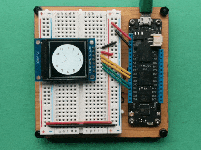
Watchface Example
For example, the following code renders a clock face using a number of the primitives mentioned above:
int hour = 0;
int minute = 0;
int tick = 0;

async Task DrawClock()
{
    graphics.Clear(true);

    hour = 8;
    minute = 54;
    DrawWatchFace();
    while (true)
    {
        tick++;
        await Task.Delay(1000);
        UpdateClock(second: tick % 60);
    }
}
void DrawWatchFace()
{
    graphics.Clear();
    int hour = 12;
    int xCenter = graphics.Width / 2;
    int yCenter = graphics.Height / 2;
    int x, y;

    graphics.DrawRectangle(0, 0, graphics.Width, graphics.Height, Color.White);
    graphics.DrawRectangle(5, 5, graphics.Width - 10, graphics.Height - 10, Color.White);

    graphics.CurrentFont = new Font12x20();
    graphics.DrawCircle(xCenter, yCenter, 100, Color.White, true);
    for (int i = 0; i < 60; i++)
    {
        x = (int)(xCenter + 80 * Math.Sin(i * Math.PI / 30));
        y = (int)(yCenter - 80 * Math.Cos(i * Math.PI / 30));

        if (i % 5 == 0)
        {
            graphics.DrawText(hour > 9 ? x - 10 : x - 5, y - 5, hour.ToString(), Color.Black);
            if (hour == 12) { hour = 1; } else { hour++; }
        }
    }

    graphics.Show();
}
void UpdateClock(int second = 0)
{
    int xCenter = graphics.Width / 2;
    int yCenter = graphics.Height / 2;
    int x, y, xT, yT;

    if (second == 0)
    {
        minute++;
        if (minute == 60)
        {
            minute = 0;
            hour++;
            if (hour == 12)
            {
                hour = 0;
            }
        }
    }

    graphics.Stroke = 3;

    //remove previous hour
    int previousHour = (hour - 1) < -1 ? 11 : (hour - 1);
    x = (int)(xCenter + 43 * Math.Sin(previousHour * Math.PI / 6));
    y = (int)(yCenter - 43 * Math.Cos(previousHour * Math.PI / 6));
    xT = (int)(xCenter + 3 * Math.Sin((previousHour - 3) * Math.PI / 6));
    yT = (int)(yCenter - 3 * Math.Cos((previousHour - 3) * Math.PI / 6));
    graphics.DrawLine(xT, yT, x, y, Color.White);
    xT = (int)(xCenter + 3 * Math.Sin((previousHour + 3) * Math.PI / 6));
    yT = (int)(yCenter - 3 * Math.Cos((previousHour + 3) * Math.PI / 6));
    graphics.DrawLine(xT, yT, x, y, Color.White);
    //current hour
    x = (int)(xCenter + 43 * Math.Sin(hour * Math.PI / 6));
    y = (int)(yCenter - 43 * Math.Cos(hour * Math.PI / 6));
    xT = (int)(xCenter + 3 * Math.Sin((hour - 3) * Math.PI / 6));
    yT = (int)(yCenter - 3 * Math.Cos((hour - 3) * Math.PI / 6));
    graphics.DrawLine(xT, yT, x, y, Color.Black);
    xT = (int)(xCenter + 3 * Math.Sin((hour + 3) * Math.PI / 6));
    yT = (int)(yCenter - 3 * Math.Cos((hour + 3) * Math.PI / 6));
    graphics.DrawLine(xT, yT, x, y, Color.Black);
    //remove previous minute
    int previousMinute = minute - 1 < -1 ? 59 : (minute - 1);
    x = (int)(xCenter + 55 * Math.Sin(previousMinute * Math.PI / 30));
    y = (int)(yCenter - 55 * Math.Cos(previousMinute * Math.PI / 30));
    xT = (int)(xCenter + 3 * Math.Sin((previousMinute - 15) * Math.PI / 6));
    yT = (int)(yCenter - 3 * Math.Cos((previousMinute - 15) * Math.PI / 6));
    graphics.DrawLine(xT, yT, x, y, Color.White);
    xT = (int)(xCenter + 3 * Math.Sin((previousMinute + 15) * Math.PI / 6));
    yT = (int)(yCenter - 3 * Math.Cos((previousMinute + 15) * Math.PI / 6));
    graphics.DrawLine(xT, yT, x, y, Color.White);
    //current minute
    x = (int)(xCenter + 55 * Math.Sin(minute * Math.PI / 30));
    y = (int)(yCenter - 55 * Math.Cos(minute * Math.PI / 30));
    xT = (int)(xCenter + 3 * Math.Sin((minute - 15) * Math.PI / 6));
    yT = (int)(yCenter - 3 * Math.Cos((minute - 15) * Math.PI / 6));
    graphics.DrawLine(xT, yT, x, y, Color.Black);
    xT = (int)(xCenter + 3 * Math.Sin((minute + 15) * Math.PI / 6));
    yT = (int)(yCenter - 3 * Math.Cos((minute + 15) * Math.PI / 6));
    graphics.DrawLine(xT, yT, x, y, Color.Black);
    //remove previous second
    int previousSecond = second - 1 < -1 ? 59 : (second - 1);
    x = (int)(xCenter + 70 * Math.Sin(previousSecond * Math.PI / 30));
    y = (int)(yCenter - 70 * Math.Cos(previousSecond * Math.PI / 30));
    graphics.DrawLine(xCenter, yCenter, x, y, Color.White);
    //current second
    x = (int)(xCenter + 70 * Math.Sin(second * Math.PI / 30));
    y = (int)(yCenter - 70 * Math.Cos(second * Math.PI / 30));
    graphics.DrawLine(xCenter, yCenter, x, y, Color.Red);
    graphics.Show();
}
Executing this code would result in something similar to the following:

Sample Applications
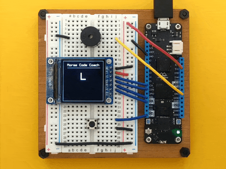
You can check these MicroGraphics Samples on Hackster that you can try out yourself.
 | Working with Graphics on a ST7789 Display Using Meadow |
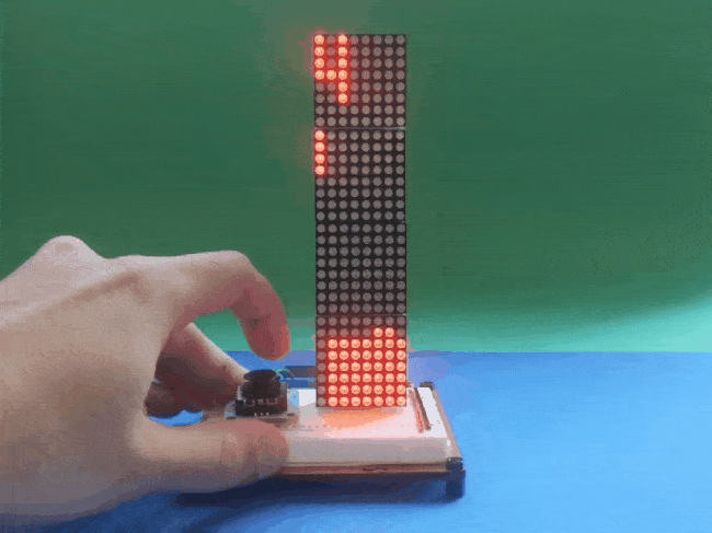 | Make Your Own Tetris Game with Meadow |
 | Train your Morse Code spelling skills with Meadow |