Power IO
Powering the Meadow F7 Feather
The Meadow F7 Feather development board is designed such that it can be powered by supplying the appropriate voltage to either the USB connector, or the 5V or 3.3V power rails.
Battery Charging Circuit
Supplying voltage via either the USB connector or 5V rail is effectively the same; it will output 3.3V on the 3V3 power rail, and enable the battery charging circuit, which will charge any standard 3.7V LiPo/LiIon battery.
To use a battery, you can either hook it to the JST-PH battery connector, or wire it directly to the VBAT and GND pins on the header. Both Adafruit and SparkFun have a good selection of LiPo/LiIon batteries that will work.
The battery charging circuit will supply a battery with up to 200mA of current (at up to 4.2V).
If you supply voltage only to the 3.3V power rail, the board will operate as expected, but the battery charging circuit will not be enabled and the 5V power rail will only be at 3.3V.
Power Budget
When powered by either USB connector or the 5V rail, the amount of combined 3.3V current available onboard (including the 3V3 power rail, MCUs, and IO peripherals) is limited, and is known as the power budget.
When powered via the USB connector, the budget is limited only by the 3.3V power regulator, which is good for 800mA of output. However, on revision 1.c of the board, when power input comes from the 5V rail, it's limited by a diode that has a 500mA maximum power throughput. Therefore, the onboard 3.3V power budget is as follows:
| Revision | Power Input | Budget |
|---|---|---|
1.c | USB | 800mA |
1.c | 5V | 500mA |
1.d | USB | 800mA |
1.d | 5V | 800mA |
However, in practice, a typical USB port is only rated to deliver 500mA of power. Some USB charging adapters will deliver much more than this, however.
You can manually upgrade a v1.c board to the v1.d version that can handle 800mA of current via the 5V rail by swapping out the following diode with a BAT60AE6327HTSA1:

Nominal Power Usage
You should generally reserve up to 400mA of the power budget for onboard functionality including both MCUs, RAM, and flash. This leaves, at a minimum, 100mA for peripherals, including anything drawing power from the IOs on the board.
Peripheral Usage
In addition to the overall power budget, the amount of power being delivered to peripherals via the IO pins must be considered. There is both an overall maximum that the MCU can drive, as well as a per pin maximum.
On the Meadow F7, there is a 25mA per IO maximum, and a total maximum of 120mA.
Battery Charger Usage
The battery charging circuit is hooked directly to the USB power rail. When powering Meadow via USB and charging a battery, the battery charging circuit will pull up to 200mA. This means you should subtract 200mA from your USB power budget. For example, if you're powering Meadow with a USB power supply that can deliver 0.75A at 5V, you should subtract 200mA from the USB power budget. The Meadow board will have 550mA available.
The battery charging circuit is also connected to the 5V rail via a diode. You can charge a battery when powering Meadow via the 5V rail. However, this will cause up to 200mA to flow through the 5V rail reducing your 5V power budget. This is important because Meadow has a current limit on the 5V rail, 500mA for 1.c boards and 800mA for 1.d boards. You'll only be able to safely use and additional 300mA for 1.c boards and 600mA for 1.d boards regardless of the available current of the external power supply.
Real-Time Clock (RTC)
The STM32F7 is equipped with a real-time clock (RTC), which, when set, will retain the system time as long as the the board has power. If the board will have intermittent power, as when powered by a solar panel, having a battery hooked up to the board will ensure the RTC will not lose the time.
Hardware Pins

Reset (RST)
The reset pin is used to do an MCU system reset. If you pull this pin LOW (to GND) momentarily, the MCU will reboot, clearing out it's volatile registers. The RST button on the board does exactly this.
Note that as long as the board still has power, the RTC will continue to keep time without resetting.
3.3V Power Rail (3V3)
The 3.3V power rail is exposed via the 3V3 header pin.
Analog Reference (AREF)
The analog reference (AREF) pin provides a reference voltage for the Analog to Digital Converter (ADC) to compare against. Typically, this should be supplied with 3.3V, so as a convenience, the AREF pin is actually connected to the 3.3V rail via 0Ω resistor that is located next to the D08 pin, just below the main MCU:

If you need to provide a different analog reference voltage, make sure to remove that resistor before hooking AREF to your voltage reference.
Ground (GND)
The ground rail (GND) provides a common 0V voltage sink and reference. It's important to make sure all connected peripherals are tied into this ground, otherwise they may not operate correctly.
Battery (BAT)
The battery pin (BAT) provides an alternative positive terminal connection for an external battery or power source to the built-in JST-PH battery connector. If using the BAT pin, make sure to tie the negative terminal of the battery to the board ground (GND).
Enable (EN)
The enable pin (EN) serves as a sort of power switch for the board. By default, it is pulled HIGH (3.3V), but when pulled LOW (0V), it will disconnect most of the power to the MCU. However, it will not disconnect backup power to the MCU, so that it will keep the RTC going and keeping time.
To create a power switch for the development board, hook the EN pin to a switch that sinks to GND (0V) when in the OFF position, as shown in the following schematic:
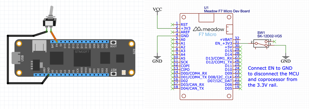
5V Power Rail (5V)
The 5V power rail is exposed via the 5V header pin.