Analog I/O
In modern digital electronics, we often deal with finite states of HIGH or LOW, which represent digital 1/0, or On/Off, respectively. However, there are many sensors or other integrations that communicate not in binary, but in a range of voltages. For instance, a TMP35 analog temp sensor might output 0V when it's reading an ambient temperature of 0ºC, 1.6V @ 50ºC, and 3.3V @ 100ºC.
Analog ports are specifically design for this scenario, and are able to operate throughout a specified range of voltages, in both an input (reading) and output (writing) capacity.
On the Meadow F7 Feather, analog signals are written or read with a 12-bit resolution, which means that the total range of voltage values are divided by 4,096 steps.
Meadow has the capabilities to both read and write analog signals, but presently only the input/read functionality is exposed via API.
Consume higher-speed analog data
Note that analog ports provide a rich system for consuming analog inputs. The data consumed this way can be limited to a few samples per second. You can consume high-speed analog input data with AnalogInputArray through a simplified API.
Samples
For sample Meadow applications that illustrate both the basic usage of analog ports and high-speed analog data acquisition using an analog input array, check out the IO Sample apps in the Meadow.Samples repo.
Analog Input
Analog input is converted to a digital value via the onboard Analog to Digital Converter (ADC), which is accessed via an AnalogInputPort, and created from a device that implements IAnalogInputController:
IAnalogInputPort analogIn = Device.CreateAnalogInputPort(Device.Pins.A02);
Getting the voltage value via the Read() method
Once the analog input port has been created, the voltage input can be read on a one-off fashion via the Read() method:
Voltage voltage = await analogIn.Read();
Events and IObservable API
As with other input APIs, the Analog input APIs support both classic .NET events and the IObservable pattern, for advanced notification filtering.
Classic .NET Events
For example, the following code illustrates subscribing to the Updated event to read the voltage on a more regular basis:
analogIn.Updated += (s, result) => {
    Console.WriteLine($"Analog event, new voltage: {result.New.Volts:N2}V, old: {result.Old?.Volts:N2}V");
};
analogIn.StartUpdating();
Filterable Observers
For more advanced filtering, or to use reactive-style programming, an Observer can be created and subscribe to notifications, with an optional filter. For example, the following code creates a filterable observer than is only notified when when the voltage changes by at least 0.1V:
var observer = IAnalogInputPort.CreateObserver(
    handler: result => {
        Console.WriteLine($"Analog observer triggered; new: {result.New.Volts:n2}V, old: {result.Old?.Volts:n2}V");
    },
    // filter is optional. in this case, we're only notifying if the
    // voltage changes by at least `0.1V`.
    filter: result => {
        if (result.Old is { } oldValue) {
            return (result.New - oldValue).Abs().Volts > 0.1;
        } else { return false; }
    }
);
analogIn.Subscribe(observer);
analogIn.StartUpdating();
Because the filter is optional, passing null for it will result in getting notified every time the analog input port is sampled.
For more information, see the Events and IObservable guide.
StartUpdating()/StopUpdating()
In order to get events or notifications, the StartUpdating() method must be called. By default, it will automatically oversample (take multiple samples and average them), and has optional parameters which allow you to control whether or not it will oversample, how many samples to take, as well as the duration between samples and between readings:
void StartUpdating(int sampleCount = 10, int sampleIntervalDuration = 40, int standbyDuration = 100);
For more information on oversampling, see the Working with Sensor guide.
Input Voltage Tolerance and Sample Circuit
When using the analog input ports, your circuit should take into account two considerations:
- Input Voltage Tolerance - The maximum voltage that the ADC can handle is
3.3V. - Value Normalization - A small capacitor can be used to help normalize the input voltage.
Input Voltage Tolerance
It's important to note that unlike the digital inputs (which are 5V tolerant), the analog inputs on the F7 Feather are only 3.3V tolerant, meaning any input signals above 3.3V may damage the chip. If you expect input signals to exceed 3.3V, there are two ways to protect the input.
Dividing Input Voltage
If your sensor regularly operates at a higher voltage range, for instance, if it's a 5V sensor, a two resistor voltage divider should be used to "divide" the voltage down from 5V to 3.3V.
Transient Voltage Suppression
Additionally, it's important to protect the ADC from occasional voltage spikes, typically by using a Diode and a resistor as illustrated in this tutorial
Voltage "Storage" and Normalization
Finally, a small capacitor, typically 0.1µF, can be used to "store" the voltage input to provide a more normalized voltage value if the input is being read (sampled), very often, which can deplete the circuit of the voltage value. This capacitor will also help to smooth out the signal if there is noise on the line, or the sensor being read is noisy.
Example Circuit
For example, the following circuit illustrates these concepts in action. It uses as an analog solar intensity gauge that can read the current output of a solar panel (6V_Solar):
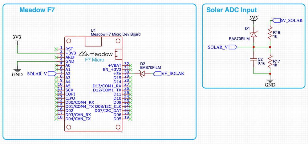
Examining it, it has several important features:
- Voltage Divider - The output of the solar panel comes in on the
6V_Solarnet and the first thing that happens is that it hits a voltage divider (R16andR17) that divides the input voltage in half by sinking half of it toGND. Typically, solar panels output a maximum of6.5V, so by dividing that in half, at full power the ADC will only receive3.25Vat maximum. - Transient Voltage Suppression -
D1in the diagram is a diode that connects the divided voltage output to the3V3rail. As long as the voltage to that diode is less than the voltage on the3V3rail, it will go into the ADC as, expected. However, if a voltage spike occurs and that voltage exceeds the3V3rail, for instance, if there's a static electricity discharge from the solar panel, it will dump any excess voltage onto that rail. - Smoothing Capacitor -
C2in the diagram is a0.1µfcapacitor that will store the input voltage and resist fast changes to the voltage level, providing a smoother value.
Additionally, there is one more interesting component in the circuit, D2, which is a diode that will make sure when the Meadow board is plugged into USB, the 5V rail power isn't fed into the solar intensity gauge circuit.
Analog Reference (AREF)
The analog reference (AREF) pin provides a reference voltage for the Analog to Digital Converter (ADC) to compare against. Typically, this should be supplied with 3.3V, so as a convenience, the AREF pin is actually connected to the 3.3V rail via 0Ω resistor that is located next to the D08 pin, just below the main MCU:

If you need to provide a different analog reference voltage, make sure to remove that resistor before hooking AREF to your voltage reference.
Analog Output
Analog output can be generated via the Digital to Analog Converter (DAC) on the Meadow device. This feature is not currently exposed, and these docs will be updated when we ship it.