Meadow.Foundation.ICs.IOExpanders.Mcp23x08
| Mcp23x08 | |
|---|---|
| Status | |
| Source code | GitHub |
| Datasheet(s) | GitHub |
| NuGet package |  |
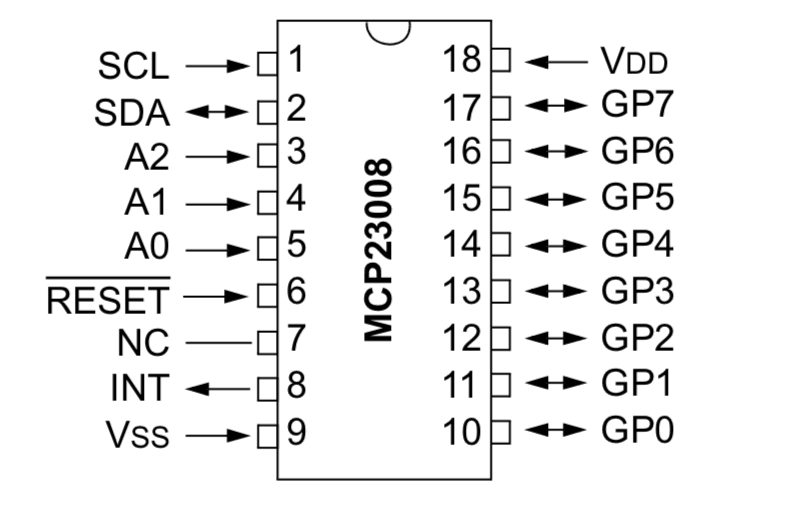
The MCP23008 chip is an 8-bit (8 port) digital I/O expander chip that uses I2C to communicate. It can be used to add additional digital input and output ports to Meadow and can be combined with up to eight MCP23008 chips in total, providing 64 additional ports.
MCP23008 is a ubiquitous chip in the hardware world and is the typical interface chip for common I2C LCD backpacks, with the 74595 chip being the typical interface chip for SPI LCD backpacks.
MCP Chip Family
In addition to the MCP23008, the MCP family of chips includes; the MCP23017, which is a 16-bit version of the MCP23008, offering 16 digital ports in total, and the MCP23S08 and MCP23S017 which are SPI versions of the MCP23008 and MCP23017, respectively.
Chip Addressing
The I2C address of the chip is configurable via the address pins and is in the binary form of 0100[A2][A1][A0], where A2, A1, and A0 refer to the three address pins on the chip:
For example, if all address pins were tied to ground, then the address of the chip would be 0100000 in binary, or 0x20 in hex, and 32 in decimal.
The I2C addresses can then be as follows, where 0 represents an address pin connected to ground, and 1 represents an address pin connected to 3.3V:
| Address Header | A2 | A1 | A0 | Resulting Hex Address | Resulting Decimal Address |
|---|---|---|---|---|---|
0100 | 0 | 0 | 0 | 0x20 | 32 |
0100 | 0 | 0 | 1 | 0x21 | 33 |
0100 | 0 | 1 | 0 | 0x22 | 34 |
0100 | 0 | 1 | 1 | 0x23 | 35 |
0100 | 1 | 0 | 0 | 0x24 | 36 |
0100 | 1 | 0 | 1 | 0x25 | 37 |
0100 | 1 | 1 | 0 | 0x26 | 38 |
0100 | 1 | 1 | 1 | 0x27 | 39 |
Because there are 8 address possibilities, it's possible to put 8 MCP23008 chips on a single I2C bus.
To make this simpler, when instantiating an MCP23008 object, there is a constructor overload that takes the address pin configurations instead of an address, so that Meadow.Foundation uses the appropriate address based on the pins, instead of requiring a pre-computed address.
Other Pins
In addition to the address pins, there are a number of other pins that must be connected up:
- Not Reset - The
RESETpin is actually a "Not Reset." The line above "Reset" means "not." So unless that pin is pulled high (3.3V), the chip will reset itself at random times and you'll get connection errors. - SCL and SDA - The
SCLandSDApins are the I2C clock and data pins and go to theSCandSDpins on the Meadow, respectively. Each of these should also generally be pulled high (3.3V) via a4.7kΩresistor. See the I2C guide for more information. - INT - The
INTpin is for interrupt notifications, and is only necessary when using the GPIO pins in input mode and you want an event raised when the input value changes. - VSS and VDD - These go to ground and 3.3V power, respectively, and power the chip.
Code Example
Mcp23x08 _mcp;
public MeadowApp()
{
    TestOutputs();
}

void TestOutputs()
{
    InitializeOutputs();

    while (true)
    {
        TestBulkDigitalOutputPortWrites(20);
        TestDigitalOutputPorts(2);
    }
}

void InitializeOutputs()
{
    IDigitalInputPort interruptPort =
        Device.CreateDigitalInputPort(
            Device.Pins.D00,
            InterruptMode.EdgeRising);
    // create a new mcp with all the address pins pulled low for
    // an address of 0x20/32
    _mcp = new Mcp23x08(Device.CreateI2cBus(), false, false, false, interruptPort);
}

void TestDigitalOutputPorts(int loopCount)
{
    var out00 = _mcp.CreateDigitalOutputPort(_mcp.Pins.GP0);
    var out01 = _mcp.CreateDigitalOutputPort(_mcp.Pins.GP1);
    var out02 = _mcp.CreateDigitalOutputPort(_mcp.Pins.GP2);
    var out03 = _mcp.CreateDigitalOutputPort(_mcp.Pins.GP3);
    var out04 = _mcp.CreateDigitalOutputPort(_mcp.Pins.GP4);
    var out05 = _mcp.CreateDigitalOutputPort(_mcp.Pins.GP5);
    var out06 = _mcp.CreateDigitalOutputPort(_mcp.Pins.GP6);
    var out07 = _mcp.CreateDigitalOutputPort(_mcp.Pins.GP7);

    var outs = new List<IDigitalOutputPort>() {
        out00, out01, out02, out03, out04, out05, out06, out07
    };

    foreach (var outie in outs) {
        outie.State = true;
    }

    for(int l = 0; l < loopCount; l++) {
        // loop through all the outputs
        for (int i = 0; i < outs.Count; i++) {
            // turn them all off
            foreach (var outie in outs) { outie.State = false; }

            // turn on just one
            outs[i].State = true;
            Thread.Sleep(250);
        }
    }

    // cleanup
    for (int i = 0; i < outs.Count; i++) {
        outs[i].Dispose();
    }
}

void TestBulkDigitalOutputPortWrites(int loopCount)
{
    byte mask = 0x0;

    for (int l = 0; l < loopCount; l++) {

        for (int i = 0; i < 8; i++) {
            _mcp.WriteToPorts(mask);
            mask = (byte)(1 << i);
            Thread.Sleep(5);
        }
    }
}
Sample project(s) available on GitHub
Wiring Example
